- GOLF COURSE EQUIPMENT
- SPORTS TURF
- INDUSTRIAL DIESEL ENGINES
- MARINE ENGINES
- GENERATOR DRIVE ENGINES
- DRIVETRAIN EQUIPMENT
- TRACTORS & MOWERS
- CONSTRUCTION
- UTILITY VEHICLES & ACCESSORIES
- ATTACHMENTS & ACCESSORIES
Features
CommandTouch™ multi-speed feederhouse drive provides extra high-torque drive capacity
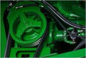 CommandTouch multi-speed feederhouse drive
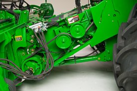 Left-hand side of feederhouse
The CommandTouch multi-speed feederhouse drive includes large internal reverser components to match the loads associated with larger chopping corn heads.
The drive system includes the following components to provide drive capacity exceeding that of the high-torque variable feederhouse drive:
-
Large internal reverser gearbox components
-
Multi-speed feederhouse drive transmission
-
High-tensile-strength belts (transmits power from the multi-speed drive transmission to the feederhouse back shaft)
When the combine is connected to a corn head, the operator can select the feederhouse speed that best matches crop conditions and ground speed on the go using the feederhouse speed button on the multi-function control handle.
When the engine is operating at 2100 rpm, the feederhouse back-shaft speed for each of the five transmission speeds will be as follows:
First gear |
490 rpm |
| Second gear | 550 rpm |
| Third gear | 600 rpm |
| Fourth gear | 670 rpm |
| Fifth gear | 750 rpm |
The feederhouse back-shaft speed (rpm) and current gear selection can be viewed by the operator in the CommandARM™ display and is on the set-point combine adjustment functions of S-Series Combines.
High-performance S-Series EvenMax cleaning system
The EvenMax cleaning system has a large cleaning shoe area and a unique, multi-leveled shoe design that provides customers with superior shoe capacity. The result is a high-performance cleaning system that reduces slope sensitivity while delivering results.
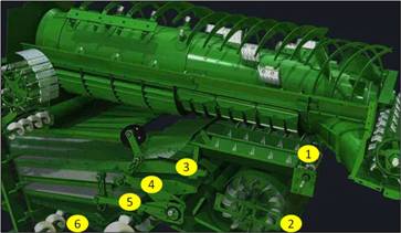 S-Series EvenMax cleaning system

The EvenMax cleaning system begins with conveyor augers located beneath the concave, where the volume of threshed material is highest, to evenly move material onto the cleaning shoe (1). The deep auger troughs provide uniform distribution of material to the cleaning shoe with less bunching, even on sloping terrain and when harvesting up or down hills.
Once grain is on the cleaning shoe, the raised-center front chaffer cleans up to 40 percent of free grain before it reaches the main chaffer (3). High-velocity air from the cleaning fan elevates any light material traveling over the end of the front chaffer, resulting in more aggressive separation of chaff and increased cleaning performance (2). The main chaffer provides grain separation from chaff as the grain passes through the main chaffer to the sieve (4).
The sieve provides proper sizing of grain from material other than grain (5). Any grain that passes through the sieve is elevated to the grain tank while some grain or material other than grain flows to the tailings return system for reprocessing. On S650, S660, and S670 Combines, the tailings material is directed back into the threshing section of the separator for additional threshing. The tailings on the S680 and S690 Combines is directed to the active tailings return system for additional threshing then directs the material back on the return pan then onto the main chaffer for additional cleaning (6).
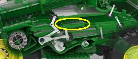 S690 cleaning shoe with extended chaffer circled

For S680 and S690 Combines, the S-Series cleaning system also includes an extended front chaffer. The extended front chaffer (circled) provides an additional cleaning capacity to match the high throughput of the S-Series separator.
Isochronous engine governor enhances overall capacity and efficiency
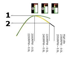 Isochronous engine governor

- Maximum power
- Rated power
Black line = Model year 2011 engine curve (with separator on)
Yellow line = Model year 2012 engine curve (with separator on)
Green line = Unloading (with separator on)
The isochronous engine governor keeps engine speed constant until rated engine power is exceeded. Due to the constant engine speed driven components remain at constant speed too, which enhances the combine overall capacity as well as efficiency. This is gained by preventing over blowing of shoe in low-load conditions such as starting a filed, down crop conditions when leaving, entering a path, that can either end in higher shoe losses or in dirty grain tank samples.
Main benefits of the isochronous engine governor include:
- Constant engine speed equals increased overall machine performance
- Reduced engine operating speed equals less fuel usage
- Consistent engine speed equals better durability
The cleaning shoe speed is directly proportional to the engine speed. The cleaning shoe performs best as it approaches its maximum operating speed. With non-isochronous engines, the shoe speed was calibrated to limit the maximum shoe speed proportionally to the maximum engine speed with no load. This left the shoe speed subject to falling below the optimal cleaning speed in tougher, heavier load conditions. The isochronous governor manages and maintains the engine speed throughout the array of crop conditions, leading to a more consistent, better-performing cleaning system.
The isochronous governor electronically activates only when the separator or unloading auger is engaged. Normal engine operation (higher idle) will be present when the machine does not have the separator or unloading auger engaged.
Power meter display
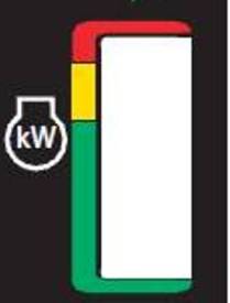 Power meter

Previously, engines without isochronous governors would decrease the crankshaft speed when load was applied to the engine. Operators could hear when this happened, which gave them an understanding of the amount of power the engine was being required to output. Since the isochronous governor maintains a constant crankshaft speed independently of the engine load, a display is created to aid in the operator’s understanding of the power output by the engine.
A power meter in the cab gives the operator a visual reference of how much power is being used, similar to how changes in engine speed are displayed. The display features a bar graph, which shows the operator how much engine power is being used at any time.
- Green – 35 to 100 percent engine load (14 bars)
- Yellow – 101 to 110 percent engine load (4 bars)
- Red – 111 to 114 percent engine load (2 bars)
As long as the combine is operated in the green range, it is running below rated power at constant rpms when reaching the yellow area it exceeds rated power engine rpm starts to drop. When reaching the red area, the operator is informed that the machine is close to reaching maximum power, so the operator should pay attention to the throughput of the machine.
Closed-center hydraulics system overview
Closed-center hydraulic pump
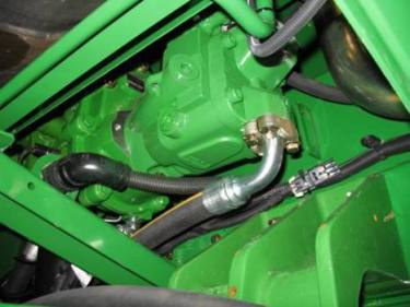 Main hydraulic pump
The main hydraulic functions on the S680 and S690 Combines utilize a closed-center hydraulic system. The system is equipped with a pressure-flow compensated (PFC) pump that varies the pressure and flow required to meet the immediate needs of the main hydraulic functions on the combines.
The pump only produces enough oil pressure to meet the system’s demands as they occur. As a result, the pump is always in a low-pressure standby mode. The benefits of having low-pressure standby are:
- Runs cooler than conventional open-center hydraulic systems
- Less horsepower required
- Easier engine starting
The variable-pressure hydraulic pump is an axial piston pump and features:
- Piston-style design for quick response
- 3100-psi high-capacity output
- Solid robust design
- Bigger front-end attachment lift capacity
- Low noise (due to pressure flow on demand)
The closed-center system is ideally suited for S680 and S690 Combines that typically operate larger/wider headers because it:
- Provides pressure-based header float to better maintain the constant ground pressure required by wider, heavier heads
- Features higher-flow valve blocks for the fast hydraulic response needed with larger heads
- Provides improved precision control (for the operator)
Header height (raise/lower) valve block with pressure control
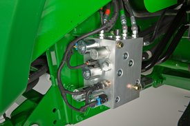 Header height valve block
The closed-center hydraulic system utilizes a separate header height (feederhouse raise/lower) control valve that features integrated pressure control.
The header height valve eliminates the need for an accumulator in the header raise and lower hydraulic circuit and results in:
- Faster header-lift response time
- More efficient control of raising and lowering the header
The header height raise/lower control valve is located on the left-hand side of the front axle frame and provides:
- Close location to the feederhouse lift cylinders for faster raise/lower response
- Easy-to-replace cartridge valve design (no need to replace the whole valve)
- A 26 percent higher-flow capacity compared to the open-center design for easier lifting of heavier or wider heads
The header-height-valve block controls flow rates for:
- Feederhouse raising and lowering
- Header height sensing
- Header float
Primary control valve
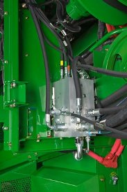 Primary-control-valve block
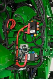 Primary valve solenoids and wire harness
The primary-control-valve block for the closed-center hydraulic system is located on the left-hand side of the separator body. The primary-control-valve block features a split electrical and valve design in that the valve block is placed on the rear side of a bulkhead panel and the electrical portion (solenoids, harnessing, etc.) is placed on the front side of the same panel.
The split design allows for easier serviceability while providing centrally located diagnostic ports. The primary-control-valve block controls flow for:
- Unloading auger swing
- Variable threshing speed
- Folding grain tank extension/covers (if equipped)
The primary valve also features easy-to-replace cartridge valve technology (no need to replace the entire valve).
Reel lift and lateral tilt valve block
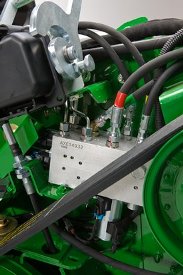 Reel lift and lateral tilt valve block
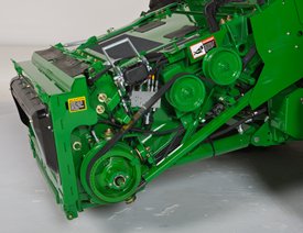 Reel-lift-valve-block location
The closed-center hydraulic system also features a separate reel lift and lateral tilt valve with proportional control. This valve provides:
- Feederhouse lateral tilt adjustment – The speed can be increased or decreased if the system is too fast or slow during manual commands
- Feederhouse lateral tilt sensitivity adjustment – This allows increase in sensitivity when in automatic mode if more response is needed. Decrease sensitivity if the system is not stable (jerky up and down)
- Close location to the header and lateral tilt (left-hand side of feederhouse) – This enables for quicker operational response
- Easy-to-replace cartridge valve design – There is no need to replace the entire valve
This valve controls flow rates for:
- Reel raise and lower
- Reel extend and retract
- Feederhouse lateral tilt position
ProDrive™ propulsion system automatically shifts between two speed ranges as ground conditions change
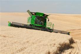 Harvesting in rolling ground and slopes

Valuable harvest time will no longer be lost shifting on hills, on slopes, and when exiting fields to start transporting. The ProDrive propulsion system is a high-capacity feature that enables John Deere S-Series Combines to maintain high levels of productivity in all terrain and ground conditions.
The system uses powershift transmission technology to automatically shift between two speed ranges as ground conditions change, to keep the combine harvesting at the desired ground speed.
Mode one can be set for typical harvesting speeds. Mode two can be used when higher speeds are needed during harvest or when transporting the combine.
The ground speed can be infinitely varied within both modes by the operator, using the multifunction control handle on the CommandARM™ armrest console. The multifunction handle regulates the high-capacity, variable hydrostatic pump and motor that drives the ground speed.
The productivity advantages of ProDrive include the following:
-
Precise control of the combine speed (when going up or down hills), without the need to continuously monitor and adjust the hydrostatic control handle
-
No need to stop to shift between transmission gears
-
Automatic powershift technology between speed ranges
-
Operator-selected maximum speed within each mode, allowing for more precise control of the combine in delicate operations (for example, when hooking up headers)
-
High-capacity, high-torque ground drive performance during harvest and transport
-
No loss of ground speed when engaging four-wheel drive (if equipped)
The ProDrive system on S-Series Combines includes an integrated Harvest Smart™ feedrate control system to provide the maximum productivity and reduce operator stress and fatigue.
ProDrive basic specifications
The ProDrive hydrostatic motor has a higher displacement than the previous hydrostatic systems.
Both the pump and motor are variable-displacement components that allow ProDrive to maintain high levels of torque to the ground throughout each of the two operating-speed ranges.
ProDrive system operation
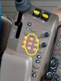 ProDrive buttons on armrest

ProDrive provides operators with superior control of the combine ground drive through the CommandARM armrest console.
Using the navigation tools on the armrest, the operator can dial in the desired maximum-attainable speed within each of the two modes.
The maximum forward speed in either range can be set from 0 to 24 mph. The maximum speed in range one cannot be set higher than the maximum speed for range two.
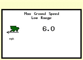 CommandTouch™ ProDrive mph screen
For example, if a maximum harvest speed of 8 mph (13 km/h) is desired and set, the full forward position of the hydrostatic control handle will deliver the speed of 8 mph (13 km/h).
This feature provides more precise and comfortable control of the combine ground speed throughout the travel range of the hydro handle.
The adjustability of the range of speed can also make maneuvering the combine in close quarters and connecting header equipment much easier.
ProDrive transmission brakes
 Park brake button
ProDrive comes equipped with hydraulic wet-disc brakes; five brake discs per side provide ample braking performance during transport or when operating on hills.
When transporting, it is recommended the two independent brakes pedals be locked together. When in field mode, the brakes pedals can be pushed individually for various terrain conditions.
When the hydro handle is moved to the neutral position, the park brake is automatically engaged to prevent unintended movement and can be locked in this mode with the touch of the park brake button on the CommandARM armrest console.
An alarm in the CommandARM display alerts the operator the park brake is engaged, if it has not been released prior to hydro handle movement. When the combine engine is turned off, the park brake is automatically applied.
The ProDrive transmission is equipped with an electrohydraulic differential lock with a four-pinion differential. Non-ProDrive combines have a two-pinion differential.
When operating in muddy, hilly terrain or in sandy conditions that may cause one of the tires to lose traction, this differential lock enables the operator to maintain productivity. If traction is lost, the operator can quickly and easily engage the differential lock by pressing the differential lock button on the CommandARM armrest console. An indicator light within the button alerts the operator that the differential locking feature is engaged.
This feature eliminates the need for the operator to control the drive wheel slip manually with the independent brake pedals. When turning, the differential lock disengages automatically if one of the brakes is applied, or if the operator presses the button to disengage the differential lock.
Flexible cab options
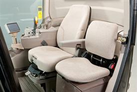 Cab view

The cab offers unsurpassed visibility, operator comfort, convenience, and productivity. The combine cab is 254-mm (10-in.) wider and 190-mm (7.5-in.) deeper than 70 Series Combines.
Deluxe cab
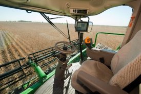 Operator station

The deluxe cab offers:
- 30 percent larger cab than the previous 70 Series Combines
- Deluxe, centered operator seat
- Breakaway, foldable cab-mounted mirrors with beacon lights
- 25 percent greater blower and increased air-quality system capacity
- Non-touch CommandCenter™ display
- Touch CommandCenter display (optional)
- Operator seat with air suspension, swivel, fore-aft attenuation
- Single-tilt steering column with telescoping controls
- Convenience outlets for power
- Telematics ready
- Power strip bank
- Business band ready
- Deluxe storage
- Map and dome lights
- AM or FM radio ready
- Tinted glass
- Air conditioner and heater
- Armrest controls
- Two-speed and intermittent front wiper
Premium cab
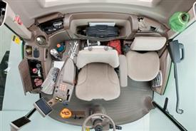 Overhead view of cab interior

The premium cab includes the deluxe cab features plus:
- Touch CommandCenter display
- Premium, leather seat with lateral attenuation and a low-frequency suspension (optional)
- Leather instructor seat with leather-wrapped steering wheel (optional)
- Dual-tilt steering column with telescoping controls
- Active refrigerator
- Premium storage
- Electric adjust, heated roof-mounted cab mirrors
- Premium radio with auxiliary input jack
- Pull-down front sunshade
Power folding grain tank extensions and covers
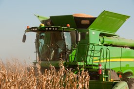 Power folding grain tank extension
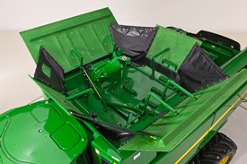 Power folding loading auger and extensions
The ability to fold the 10,600-L/14,100-L (300-bu/400-bu) grain tank is designed for height-restricted areas and ease of use on the S-Series Combines. The power folding extensions/covers are made of a water-resistant composite material to keep the grain tank dry when covers are closed without grain in the tank. The covers feature vinyl corners to achieve grain tank capacity and proper folding.
The power folding grain tank option is controlled from the CommandCenter™ armrest inside the cab. Not only do the covers fold, but the fountain/loading auger also folds with a simple touch of a button so there is no need to enter the grain tank.
The power folding grain tank extensions/covers option is available on the S660, S670, S680, and the S690 combines.
For visual comparison purposes, see the manual folding grain tank below:
![Manual folding grain tank (14,100 L [400 bu] on a S690 Combine)](https://honeycombes-ag.com.au/wp-content/uploads/2020/04/400bu_manual_gt.jpg) Manual folding grain tank (14,100 L [400 bu] on a S690 Combine)
Manual folding grain tank (14,100 L [400 bu] on a S690 Combine)

14,100-L (400-bu) S-Series grain tank
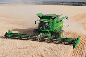 S690 with 14,100-L (400-bu) grain tank
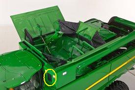 Grain tank sample door
John Deere designed the 14,100-L (400-bu) grain tank to match increasing yield trends and larger header sizes to increase total machine productivity. The 14,100-L (400-bu) grain tank comes with two grain-tank-level sensors to alert the operator when levels reach three-fourths and full. The grain-tank-levels are also tied into the beacon lights to alert grain cart drivers.
A convenient hinged door panel provides quick access to obtain a grain sample. The grain trough delivers grain right to the sampling area for increased safety when taking an early grain tank sample.
NOTE: The 14,100-L (400-bu) grain tank features heavy-duty final drives to support the weight associated with the grain tank. This larger grain tank also has specific tire recommendations and comes equipped with ProDrive™.
135-L (3.8-bu) per second unload rate
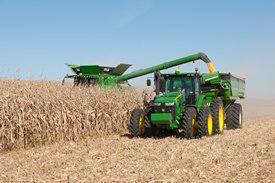 S690 with 135-L (3.8-bu) per second unload rate

The 135-L (3.8-bu) per second unload rate features an enclosed gearcase for quieter and quicker engagement. A strengthened drive chain gives the 135-L (3.8-bu) per second unload rate increased durability. The unloading system also features larger sheer bolts.
The 135-L (3.8-bu) per second unload rate features:
- Large-diameter grain tank cross augers 25.4cm (10 in.)
- Large vertical auger 43.2 cm (17 in.)
- Larger-diameter unloading auger 38.1cm (15 in.) and auger tube 43.2 cm (17 in.)
- Available in both general-purpose and extended-wear versions
Clean-grain system
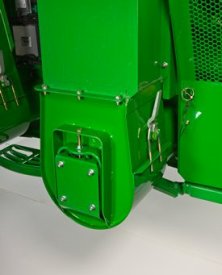 S680-S690 clean-grain elevator assembly

The large clean-grain elevator allows columns of grain to be handled by the elevator without plugging. The drive capacity in the clean-grain elevator system comes from large drive sheaves with belt wrap, large conveyor chain sprockets and a larger clean-grain cross auger.
Key features of the clean-grain elevator are as follows:
- Clean grain elevator efficiently delivers clean grain to the grain tank
- Elevator chain tension can be easily adjusted from the ground
- Hinged door allows complete and convenient grain cleanout
- Larger lower auger, boot, and heavy-duty chain on the S690
Loading auger
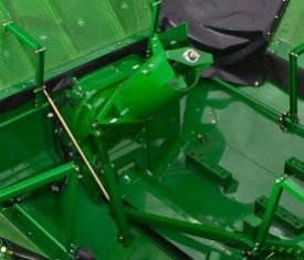 Folding loading auger in field-ready position

The grain tank loading auger ensures rapid movement of grain from the clean-grain elevator into the grain tank. The auger gearbox is an aluminum case featuring large, strong bevel gears immersed in oil for constant lubrication. An abrasive-resistant shield covers the gearcase to protect it from wear in abrasive crops.
- Positioned forward on 14,100-L (400-bu) grain tank to evenly fill grain tank
- Designed to not push against large volumes of grain when filling the tank
- Easily folds down to the transport position to reduce overall combine height
- Heavy-duty loading auger gearbox on the S690
Offers and Discounts
0% p.a. Finance Available* on Combine Parts and Servicing
Related Products
Product features are based on published information at the time of publication. Product features are subject to change without notice. Contact your local John Deere dealer for more information.

